Traffic3D assets
Note: Most assets on this page have a prefab (a premade item) within the
Assets/Resources/Modelsfolder which can be copied or used an example to create / edit your own Assets.
Traffic Lights
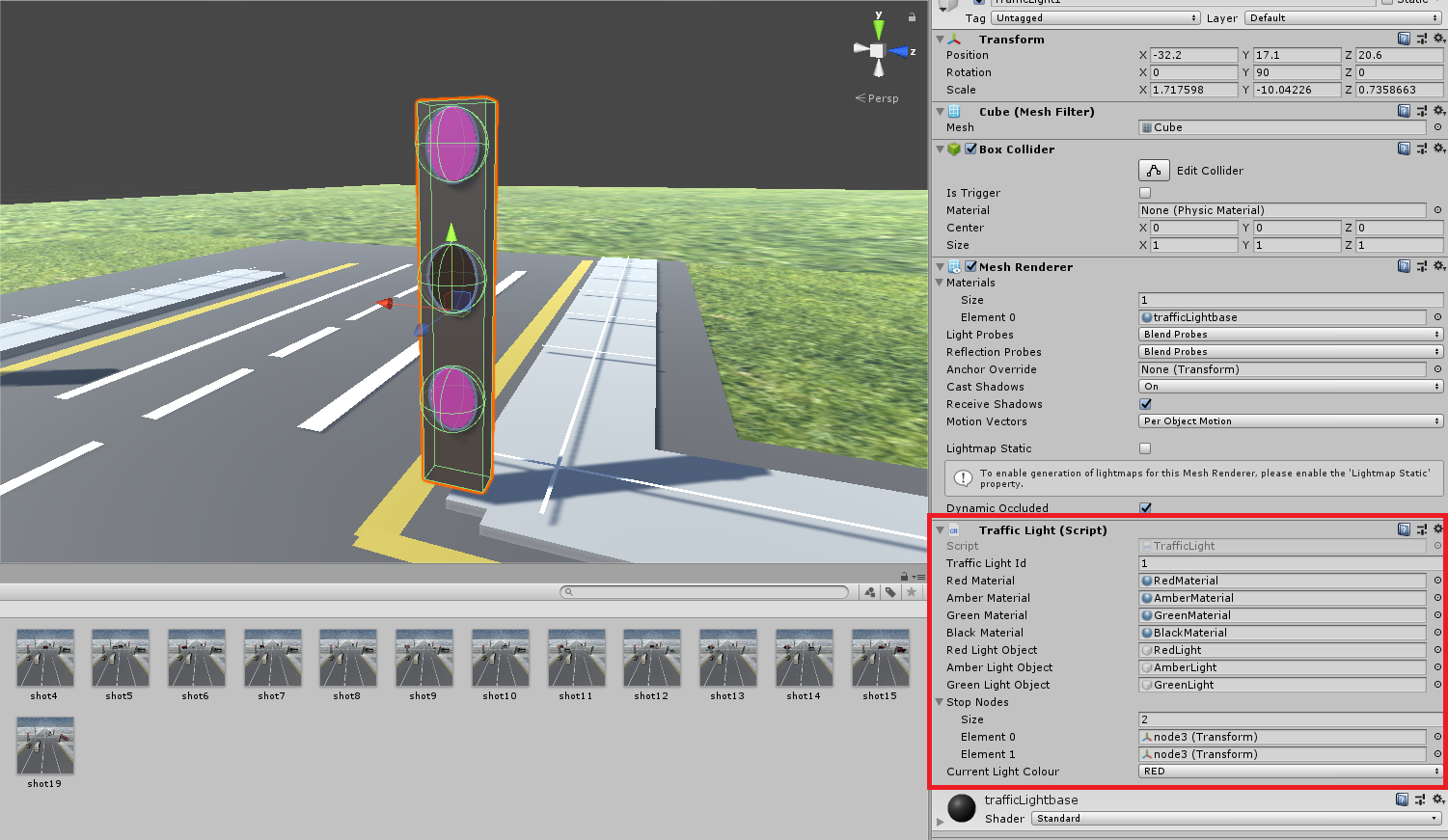
These are used to control traffic and are used within junctions, the script has the following fields:
- Traffic Light Id - The traffic light's unique number that identifies the traffic light.
- Red Material - The material of the red light when it is on.
- Amber Material - The material of the amber light when it is on.
- Green Material - The material of the green light when it is on.
- Black Material - The material of all lights when off.
- Red Light Object - The circle object for the red light (normally the top light).
- Amber Light Object - The circle object for the amber light (normally the centre light).
- Green Light Object - The circle object for the green light (normally the bottom light).
- Stop Nodes (List) - The nodes on multiple paths where the traffic light stops the vehicles (more on this later).
- Current Light Colour - The colour of the light that is currently on (e.g.
RED,AMBER,GREEN).
Vehicles
Vehicles are made up of multiple scripts with the main ones being Vehicle and VehicleSettings.
The Vehicle script generates all the necessary scripts for the vehicle to run including VehicleEngine and VehicleDriver.
The following sections give an explanation of all vehicle scripts and their related fields.
Vehicle Settings
The Vehicle Settings script is for holding vehicle properties which can be edited before and during the simulation.
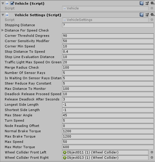
The VehicleSettings script has the following fields:
- Stopping Distance - The distance at which a sensor will signal the vehicle to stop when an object is in front of it.
- Distance For Speed Check - A list of distances to evaluate in the speed check turning algorithm (executed when taking corners).
- Corner Threshold Degrees - The threshold (in degrees) for the speed check turning algorithm to be used when calculating the speed. The bigger the angle, the faster the vehicle will take sharp turns.
- Corner Sensitivity Modifier - A value which changes the sensitivity of the speed check turning algorithm. The higher the value, the more sensitive the turning algorithm, meaning that the vehicle will slow down more around corners.
- Corner Min Speed - The minimum speed of the vehicle when going around a corner. Used by the speed check turning algorithm.
- Stop Distance to Speed - The ratio of distance to speed. Used when slowing down before traffic lights or stop lines.
- Stop Line Evaluation Distance - The distance between a vehicle and a stop line, at which a vehicle will decide whether to proceed or should stop.
- Traffic Light Max Speed on Green - The maximum speed at which a vehicle will travel through a green light.
- Merge Radius Check - The maximum distance the current vehicle will check for other vehicles. Used when merging out from stop lines.
- Number of Sensor Rays - The number of Sensor rays on the front of the vehicle.
- Is waiting on sensor rays distance - If this value is higher than the distance from vehicle to the obstacle,
Is waiting on sensor rayswill turn to true. - Steer Reduce Ray Constant - The value responsible for reducing the distance of the forward collision sensor rays for the vehicle turning algorithm.
- Max Distance To Monitor - The maximum distance for the sensor rays to monitor.
- Deadlock release proceed speed - The speed the vehicle will travel if a deadlock has been released. Normally a slow speed to represent caution.
- Release deadlock after seconds - The time in seconds for an attempt to be made to release a deadlock.
- Longest side length - The longest side of a vehicle. Value of
-1to be automatically generated but can be manually overridden. - Shortest side length - The shortest side of a vehicle. Value of
-1to be automatically generated but can be manually overridden. - Max Steer Angle - The maximum angle at which the vehicle will turn.
- Turn Speed - The speed at which the wheels will turn.
- Node Reading Offset - The forward offset of the node reader for paths.
- Normal Brake Torque - The torque which the vehicle will normally use for slowing down.
- Max Brake Torque - The maximum torque which the vehicle will normally use for slowing down.
- Max Speed - The maximum speed of the vehicle.
- Max Motor Torque - The maximum torque of the engine in a forward direction.
- Wheel Collider Front Left - The collider of the front left wheel.
- Wheel Collider Front Right - The collider of the front right wheel.
Vehicle Engine
The VehicleEngine script controls the vehicle's speed and engine status.
It has the following fields:
- Engine Status - The status of the Engine currently (e.g.
ACCELERATE,STOP,HARD_STOP). - Target Speed - The current target speed of the vehicle.
- Current Motor Torque - The current torque of the engine in a forward direction.
- Current Speed - The current speed of the vehicle.
Vehicle Driver
The VehicleDriver script holds the main loop and methods for running the vehicle.
It has the following fields:
- Is waiting on sensor rays - True if the vehicle is waiting on its front collision sensor rays. See
Is waiting on sensor rays distancefor the distance this value is triggered at. - Start Time - The time the vehicle is spawned in at.
- Start Pos - The position the vehicle is spawned in at.
- Density Count Triggered - Checked when the vehicle has passed the density measurement point.
- Debug - Shows debug information (currently displays the rays from the sensor).
- Waiting For Vehicle Ahead (Debug) - Displays the vehicle ahead which is causing the current vehicle to wait.
- Waiting For Vehicle Behind (Debug) - Displays the vehicle behind which is causing the current vehicle to wait.
Vehicle Navigation
The VehicleNavigation script controls the direction the vehicle is traveling in and holds the path of the vehicle.
It has the following fields:
- Current Node - The current node of the path the vehicle is on.
- Current Node Number - The current node number of the path the vehicle is at.
Vehicle Sensors
The VehicleSensors script manages all sensors on the vehicles which include:
- Corner Speed Sensor - Checks the current corner the vehicle is taking, calculates and sets the target speed for the vehicle.
- Deadlock Sensor - Checks for deadlocks and releases vehicle if required.
- Front Collision Sensor - Checks for obstucles in front of the vehicle and sets the target speed for the vehicle to avoid a collision.
- Merge Sensor - Checks if a vehicle can merge into it's designated path and will not collide into other vehicles.
- Speed Limit Sensor - Checks the current speed limit on the vehicle and sets the target speed accordingly.
- Stop Line Sensor - Checks for stop lines ahead, slows down vehicle and publishes an event when behind the stop line.
- Stop Node Sensor - Checks for stop nodes (Traffic Lights) ahead and slows down vehicle's approach.
- Surface Sensor - Checks for surface friction and lowers vehicle engine torque if there is low friction. This replicates slower and more cautious driving during conditions such as rain or snow.
- Traffic Light Sensor - Checks for the current traffic light status and stops the vehicle when the traffic light is red.
Note: Sensor fields are not exposed in the Unity UI, but most sensors use values from
VehicleSettingsso they are adjustable.
Extra vehicle information
Only the following fields should be filled in, the rest of the fields are filled during the simulation:
- Max Steer Angle
- Turn Speed
- Wheel Collider Front Left and Right
- Max Motor Torque
- Normal Brake Torque
- Max Brake Torque
- Number of Sensor Rays
- Max Distance To Monitor
- Node Reading Offset
- Debug
Most of these options can be left at their default values.
Vehicle Factory
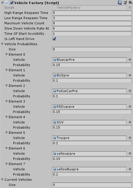
The Vehicle Factory Script has the following fields:
- High Range Respawn Time - The maximum time in simulation seconds for the next vehicle to re-spawn.
- Low Range Respawn Time - The minimum time in simulation seconds for the next vehicle to re-spawn.
- Maximum Vehicle Count - The maximum number of vehicles allowed to be in the scene at once.
- Slow Down Vehicle Rate At - The number of vehicles in the scene where the rate of spawn will slow down after this number.
- Time Of Start Invisibility - The amount of time at the start where the spawned vehicle is invisible.
- Is Left Hand Drive - Checked if the simulation should be in left-hand drive mode (as in the UK).
- Vehicle Probability (List) - A list of objects which each contain a
Vehicles and the probability of thatVehiclespawning next. Probabilities are represented as a float between0.0and1.0(inclusive). Use this to add extra Vehicles to the scene.- Vehicle - The rigidbody of the vehicle.
- Probability - The probability between
0.0 - 1.0of the vehicle spawning.
- Current Vehicles (List) - A list of
Vehicles currently in the scene.
Pedestrians
Please see the pedestrians section of this website to find out how to use pedestrians in your simulations.
The road network
A road network is a collection of nodes (RoadNode) and ways (RoadWay) where a node is a point in the scene, and a way contains an ordered list of nodes. The top of a way is the start node, and the bottom is the end node.
The way represents a direction of travel (towards the end node) for Vehicles.
RoadNodes can be marked as Start Node to allow vehicles to spawn on that node.
Please note that the option Start Node is different to "start node" and focuses on spawning vehicles, but a "start node" normally represents the first node of a way.
Multiple ways can use the same RoadNode to attach roads together.
For example a node is the last node in Way1 but is the first node in Way2.
Vehicles would then be able to drive across from Way1 to Way2.
A Vehicle Path represents a route that a vehicle drives along. Vehicle paths are created with the A* path finding algorithm, using all ways in the scene.
Vehicle Paths
Vehicle Paths are used by vehicles to reach their destination.
They are created from the Road Network of RoadNodes and RoadWays for a specific vehicle.
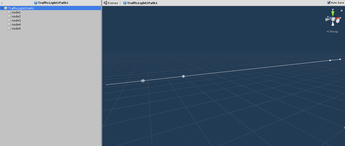
Each node represents a point along the path.
The vehicle will follow from node1 (the spawn point) to the last node which in this case is node5 where the vehicle will be destroyed.
If there is a traffic light on the path, a node (also known as a stop node) will have to be placed at the traffic light which can be easily done by either moving an existing RoadNode or creating a new one by copying and pasting a node and moving that node to the correct location (make sure the nodes are still in the correct order on the RoadWay).
Once the stop node is in the right position, assign the RoadNode to the related traffic light's Stop Nodes.
This node will be where the vehicle stops for that traffic light.
Stop Lines can also be used to control the traffic where Traffic Lights are not used.
Make sure that all paths are above ground but not too high so first node can spawn the vehicle.
To measure density, attach the DensityMeasurementPoint script to a RoadNode game object which is normally positioned after a junction.
Once the script is attached, a collider with Is Trigger checked needs to also be attached to the node game object which should be big enough to detect vehicles passing through.
Stop Lines
Stop Lines can be assigned to a RoadNode by attaching the StopLine script to the game object to allow vehicles to evaluate whether the road ahead is safe to continue.
Intersections (intersections between the current Vehicle Path and different Vehicle Paths) are evaluated to check whether approaching vehicles are a danger to the waiting vehicle.
The waiting vehicle will then continue once safe to do so.
There are currently two different types of StopLine:
- MERGE - the waiting vehicle will check all approaching vehicles, used when merging into another road.
- JUNCTION - the waiting vehicle will only check approaching vehicles to the right when driving on the left, and the left when driving on the right. Used in Junctions without Traffic Lights.
Find out how stop lines effect a vehicle's behaviour here.
Junctions
Junctions are a collection of traffic lights and pedestrian crossings which are controlled by set states. For example, in:
- Junction State 1 - Traffic Light A is Green, Traffic Light B is Red, Pedestrian Crossing C is disallowing crossings.
- Junction State 2 - Traffic Light A is Red, Traffic Light B is Green, Pedestrian Crossing C is disallowing crossings.
- Junction State 3 - Traffic Light A is Red, Traffic Light B is Red, Pedestrian Crossing C is allowing crossings.
A junction will be in only one state at a time and will change states when needed via the AI program or built-in demo. The Junction script has the following fields:
- Junction ID – A unique ID to identify the junction from others.
- Junction Camera – The camera which is assigned to the junction and is used for the AI script to set an action which is changing the Junction State.
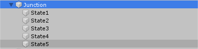
Junction States are Game Objects assigned to the parent Game Object with the Junction Script attached.
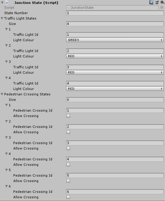
The Junction State script has the following fields:
- State Number – The number of the state which is unique to the Junction to identify the other states.
- Traffic Light States (List) – A list of the different traffic lights within the junction that need to change on this current state.
- Traffic Light Id – The traffic light ID to change.
- Light Colour – The colour for the traffic light to change to.
- Pedestrian Crossing States (List) – A list of the different Pedestrian Crossings within the junction that needs to change on the current state.
- Pedestrian Crossing Id – The pedestrian crossing ID to change.
- Allow Crossing – A Boolean which if checked will allow a pedestrian to cross on the selected pedestrian crossing during the state.
Note: Any Traffic Lights or Crossings that are missing off the list will stay in the same state.
Environment Settings
With Environment Settings, rain, snow, and night can be toggled, different lighting can be set, and surface friction can be changed too.
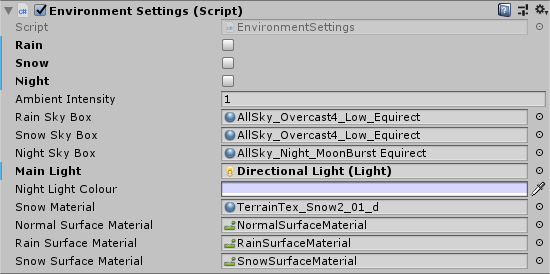
The Environment Settings script has the following fields:
- Rain – A Boolean to toggle Rain on and off.
- Snow – A Boolean to toggle Snow on and off.
- Night – A Boolean to toggle Night on and off.
- Ambient Intensity – The current lighting intensity of the scene.
- Rain Sky Box – The sky box to be used when Rain is toggled.
- Snow Sky Box – The sky box to be used when Snow is toggled (overrides rain sky box when rain and snow is toggled).
- Night Sky Box – The sky box to be used when Night is toggled (overrides rain and / or snow sky box when both or each of them are toggled with night being toggled too).
- Main Light – The main light within the scene.
- Night Light Colour – The colour of the main light when night has been toggled.
- Normal Surface Material – The physics material used as default.
- Rain Surface Material – The physics material to be used when raining.
- Snow Surface Material – The physics material to be used when snowing.
The physics material can be found in /Assets/Resources/Materials/PhysicMaterials and friction values can be changed within those objects.
Python manager
The PythonManager class controls the connection between the AI Python script and Traffic3D.
A loop is created to train the AI.
First the manager takes screenshots using all the junction cameras in the scene.
The screenshots are sent to the Python script for it to process, once processed the Python script sends the actions back for each Junction in the scene, this action is the junction state number that the junction needs to change to.
Density and Flow is then calculated and outputted in the /Assets/Results/ folder.
Rewards are then sent to the Python script for the script to process.
See the model generator page to learn more about the Python script.
The Python manager also controls the frame-rate for the scene.
PythonManager has the following fields:
- Frame Rate - when the frame rate is lower, simulation time will run faster. See the Unity API documentation for more information.
Sumo Manager
This manages the connection between SUMO and Traffic3D and allows different software to control different features. Click here learn more about SUMO and how to connect to SUMO.
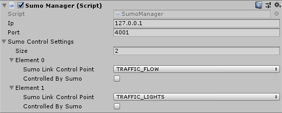
The Sumo Manager Script has the following fields:
- Ip – The IP address of the SUMO instance
- Port – The port of the SUMO instance
- Sumo Control Settings (List) – A list of the different control points that can be controlled by either Traffic3D or SUMO
- Sumo Link Control Point – The setting to control.
- Controlled by Sumo – A Boolean which if true means that the above setting is controlled with SUMO
Real time graphs
Graphs display on screen with real-time data about the simulation. These can be toggled at the start and in mid simulation. Currently there are three graphs:
- Time-Travelled – The amount of time it has taken a vehicle to travel the full distance of the journey.
- Throughput – The number of vehicles that has completed the journey during a single simulation time step.
- Delay – The amount of time it has taken for a vehicle to pass a junction.
The Graph Manager script has a Boolean field for each of the graphs above to toggle them on and off.
Camera Manager
This object takes the screenshots for the Python script and is required to be attached to all junction cameras.